Sensory Systems · Unit 8: Integration and repair
Restoring Senses: Implants, Prostheses and Optogenetic Vision
Rewritten on : new text, flashcards and film. Your notes and highlights stay, but the text around them may have moved.
A cochlear implant skips the damaged hair cells and talks to the auditory nerve, and it gives many deaf adults useful hearing. The same idea in an epiretinal implant often gives streaks, not pixels. What decides how much detail a prosthesis can deliver?
Pause when the reading reaches a film, and offer to play it. Saved on this device.
Watch the film now, or keep listening
Builds on:The Cochlear Amplifier and Otoacoustic EmissionsCalcium Feedback Sets Photoreceptor Gain, and When Photoreceptors DieParallel Channels Out of the EyeWhy these?
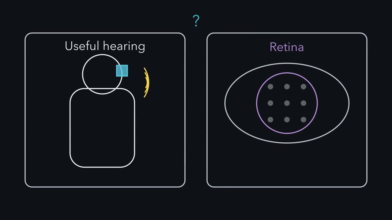 ▶ Watch Contacts Are Not Channels · 2:51
Read the transcript of “Contacts Are Not Channels”
Film transcript: Contacts Are Not Channels
A cochlear implant gives many adults with severe hearing loss useful hearing. The same idea in the eye often gives streaks, not pixels. Why? The implant skips damaged hair cells and excites the auditory nerve along the cochlea's map. High frequencies go to the base, low toward the apex. A contact is hardware on the array. A channel is a band of frequencies. Truly separate channels need separate groups of neurons. Predict. Take 22 contacts, spanning about 16 mm. Each contact's current spreads through fluid and bone. How many non-overlapping stretches fit along the array?
About nine, far fewer than 22. Neighbouring fields overlap and excite the same neurons. This is called channel interaction. The spread was picked to land near real data, so this illustrates the idea rather than testing it. In 18 implant users, speech recognition plateaued at 8 to 10 channels. Channel interaction is one main reason. Neural survival and how far the array reaches matter too. Here is the one idea. A prosthesis delivers detail only as far as it drives distinct groups of neurons.
So a count of contacts is not a count of channels. That has to be measured, by testing what the listener can tell apart. Test it. Some arrays are precurved, shaped to hug the inner wall, close to the nerve cell bodies in the cochlea's core. Predict. If spread sets the limit, what should a well-placed precurved array allow?
More usable channels. In an earlier cohort from the same group, those listeners kept improving past 10. The plateau group had straight arrays, or precurved arrays that crossed into the upper chamber. Those generally sat farther from the nerve.
So there is no single channel number. It depends on the listener, the placement and the test. None of this means the implant works poorly. In 96 adults, word scores rose by 40.5 percentage points. That was with the implant plus a hearing aid in the other ear. So ask how distinctly a device drives separate groups of neurons, and test what the listener can tell apart.
From the film
- A prosthesis delivers detail only as far as it drives distinct groups of neurons, so usable channels have to be measured by testing what the listener can tell apart.
- Current spread makes neighbouring contacts excite overlapping neurons, one main reason speech recognition plateaued at 8 to 10 channels in 18 implant users.
- There is no single channel number, since it depends on the listener, the array placement and the test, and the implant still gives large gains.
A cochlear implant with 12 to 22 contacts gives many adults with severe hearing loss useful hearing. The same engineering idea in an epiretinal implant often gives streaks, not pixels. What decides how much detail a prosthesis can deliver?
A cochlear implant is a thin array of contacts, small electrodes, threaded into the cochlea. It skips the damaged hair cells and excites the auditory nerve directly, and it is the established success of sensory prostheses. Users often describe speech through a new implant as harsh or robotic at first, and many understand much more after weeks to months of use. Still, even 22 contacts do not carry all the information normal hearing does. In the eye the gap is wider. People with an epiretinal implant, a grid of electrodes on the retina’s inner surface, were asked to draw what a single electrode made them see. They often drew elongated or distorted shapes, not the dot, the pixel, that a camera-like grid would promise.
The one idea to carry through this lesson. A prosthesis can deliver detail only as far as it drives distinct groups of neurons, each in the right place on the brain’s map. Current spread blurs neighbouring groups together, and current that reaches the wrong neurons puts the signal in the wrong place. So a count of contacts or pixels is not a count of usable channels. That has to be measured, by testing what the user can tell apart.
The idea covers spatial detail: frequency channels in the cochlea, acuity in the retina, separate patches of skin in touch. It is not a formula. Overlapping fields can still carry some extra information, and steering current between neighbouring contacts can create pitches between them. Neural survival, placement and learning also shape any one user’s score. The idea says nothing about safety, about how strong the trial evidence is, or about what pattern each group of neurons receives; that second half of the problem ends the lesson.
The lesson tests the idea on the cochlear implant and two kinds of retinal implant, then on optogenetic therapy and touch written into a nerve or cortex. It is about mechanisms and evidence, not about what any person should do.
Borrowing a map: why place coding is kind to engineers
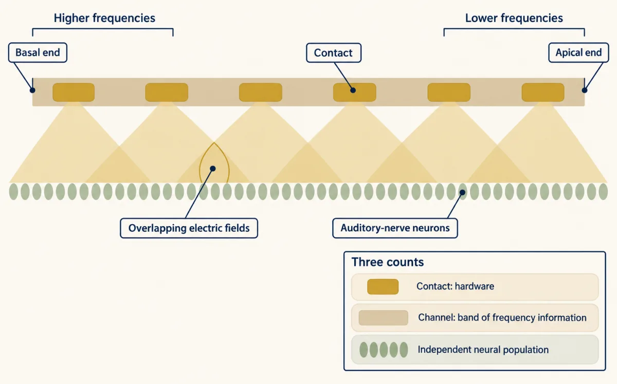
The hearing and balance lesson gave you the cochlea as a frequency map. That map is what a cochlear implant borrows. Clinical maps assign higher frequencies to more basal contacts and lower frequencies to more apical ones, which turns the place code into an addressing scheme. The cochlea is kind to engineers because it is a one-dimensional map with the nerve lying along it.
Three words are easy to blur. A contact is a piece of hardware on the array. A channel, here, is a band of frequency information assigned to a contact. What you need, for the channels to be truly separate, is an independently accessible neural population for each: its own group of auditory-nerve neurons.
Predict. Take an illustrative array of 22 contacts spaced 0.75 mm apart, spanning about 16 mm of cochlea. Current from each contact passes through fluid and bone before it reaches the nerve, so it spreads. If each contact excites neurons over about 1.75 mm, how many non-overlapping stretches of nerve fit along the array?
Check your prediction
About 16 mm ÷ 1.75 mm ≈ 9, far fewer than 22. Neighbouring contacts produce overlapping electric fields, called channel interaction, so they excite overlapping groups of neurons, and many contacts do not give the same number of independent channels. This is a toy, one-dimensional packing exercise, not a prediction of anyone’s channel count: real fields fade gradually rather than ending at an edge. The 1.75 mm is an illustrative width, picked so the arithmetic lands near what listeners show. In 18 adult implant users, tested with maps that switched on more or fewer channels, speech recognition reached a plateau at 8 to 10 channels (Berg and colleagues, 2020). So the match illustrates the idea; it does not test it. Channel interaction is one main reason for that plateau. Neural survival, the distance from contacts to neurons and how far the array reaches into the cochlea also matter.
The real test is a prediction the arithmetic was not tuned to. The nerve cell bodies the implant targets, the spiral ganglion, sit in the cochlea’s central core, the modiolus. Some arrays are straight and lie along the outer wall. Others are precurved, shaped to hug the inner wall near the modiolus. A precurved array can also be translocated: during insertion it crosses from the lower chamber, the scala tympani, into the upper one, the scala vestibuli. In the reported cohorts, straight and translocated precurved arrays generally sat farther from the modiolus than well-placed precurved ones. The 18 listeners above had straight arrays or translocated precurved arrays.
Predict. If current spread sets the limit, what should listeners with precurved arrays well placed in the scala tympani show as more channels are switched on?
Check your prediction
Contacts closer to the nerve should excite narrower groups of neurons, so these listeners should keep improving past 8 to 10 channels. In an earlier cohort from the same group, they did (Berg and colleagues, 2019). Greater channel interaction is the proposed explanation for the difference, so the plateau depends on array type and placement, as the idea says it should.
So no single channel number fits all listeners; it depends on the listener, the array placement and the test. Nor does a plateau in one test mean the extra contacts do nothing. In harder listening, extra electrodes can still help: in seven adults, going from 20 active electrodes to 8 made the speech-in-noise threshold worse, meaning speech had to be louder relative to background noise to be understood (Schvartz-Leyzac, Zwolan and Pfingst, 2017). A benefit under hard conditions does not mean each contact is independent, either.
None of this means the implant works poorly; the gains are large. CNC words are single consonant-vowel-consonant words, scored as percent correct. In 96 adults who used a hearing aid before implantation, the marginal (model-estimated) mean improvement in CNC word recognition at six months was 40.5 percentage points, tested with the implant plus a hearing aid in the other ear (Buchman and colleagues, 2020). The implanted ear alone, a separate listening condition, is under Going deeper.
Why a retinal electrode does not make a pixel
Read the transcript of “Streaks and Pixels”
Film transcript: Streaks and Pixels
Put a grid of electrodes on the retina. Do you get a grid of dots? The Argus II tried it. A camera drove 60 electrodes on the inner surface of the retina. But ganglion cell axons run across that inner surface, toward the optic disk. Predict. Axons from elsewhere run under one electrode. What does the person see when it fires?
Often not a dot. Four implant users drew elongated or distorted shapes. Each passing axon carries signals from a ganglion cell that reports a different part of the visual field. Recruit cells along a bundle, and a stretch of visual locations can be activated at once, which can produce a streak. A model of axon pathways accounted for the shapes. It is a model-supported explanation, not a recording. The current reaches neurons whose place on the map is somewhere else. So move the electrode away from the axons, and keep each field small. The PRIMA chip does both. Near-infrared light powers its pixels. Each pixel stimulates bipolar cells, and a local return electrode confines its field.
Acuity is scored in logMAR. 0 is 20/20. 1.0 is 20/200. Higher is worse. Predict. Each pixel is 100 micrometres across. If its field stays within the pixel, what acuity could it give? The conversion is on screen. The pixel limit is near 1.32 logMAR, about 20/420.
In the PRIMAvera trial, mean acuity at the implant's own resolution was 1.32 logMAR. The measured mean sits near the pixel limit. Eyes differ in size, so treat it as agreement, not a precise prediction. For the Argus II, an ideal grid would give about 20/2400. Yet its best reported grating acuity was about 20/1260. So this is an estimate, not a hard limit. Two cautions. A zoomed score adds a magnifier, not pixels. And serious device- or procedure-related events came with the benefit. Optogenetics changes the cells instead. Ganglion cells are made to express a light-gated channel, ChrimsonR. Goggles supply the bright amber light, and part of the encoding the retina would have done.
With the goggles, one patient located, counted and touched objects. Without them, the patient did not detect objects. Where current reaches the wrong neurons, percepts can be distorted. PRIMA's mean acuity sits near its pixel limit, as its design aims for. With optogenetics, the goggles' light decides which cells are driven.
From the film
- An epiretinal electrode often gives a streak rather than a dot, because current excites axons of passage that serve other places in the visual field, as a model of axon pathways accounts for.
- PRIMA places pixels beneath the retina with local return electrodes, and its mean acuity of about 1.32 logMAR sits near the pixel limit, which is agreement rather than a precise prediction.
- A zoomed score adds a magnifier, not pixels, and serious device- or procedure-related events came with the benefit.
- In one optogenetic patient the response depended on the goggle light, and one patient cannot show how often this works.
An eye is a camera, so the tempting design is a grid of electrodes that makes a grid of dots. The Argus II tried it: a camera converted images into stimulation patterns for an array of 60 epiretinal electrodes. A prospective trial tested it in 30 adults with end-stage outer-retinal degeneration, 29 with retinitis pigmentosa and one with choroideremia (da Cruz and colleagues, 2016).
Recall from the retina that ganglion-cell axons run across the retina’s inner surface toward the optic disk, which is where an epiretinal electrode sits (over the macular retina in these implants).
Predict. Axons from ganglion cells elsewhere in the retina pass under the electrode. Why would stimulating that one electrode give a streak rather than a dot?
Check your prediction
The drawings in the opening come from Beyeler and colleagues (2019): four adults with severe retinitis pigmentosa (one Argus I and three Argus II implants) drew what they saw when single electrodes were stimulated. A model that traces axon pathways across the retina accounted for the shapes: current excites axons of passage, and the percept follows the places those axons normally serve, each carrying signals from a ganglion cell that reports a different part of the visual field. Recruiting cells along a bundle of passing axons activates a stretch of visual locations at once, which can account for an elongated percept, a streak. That is a model-supported explanation of the drawings, not a direct recording of the axons.
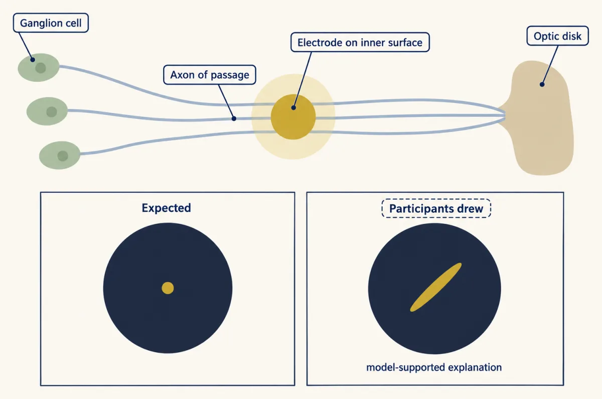
One electrode therefore does not make one pixel, and a simulation that draws a clean grid of dots overstates what the implant user sees: the current reaches neurons whose place on the map is somewhere else.
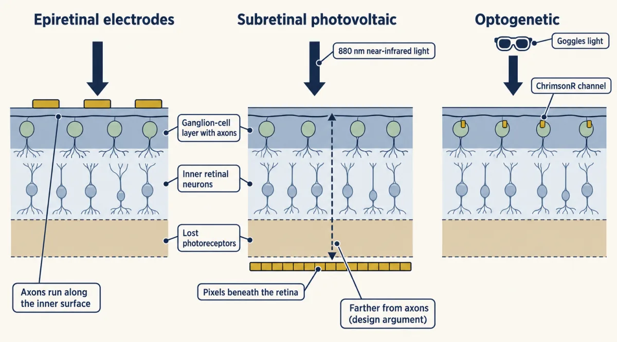
The idea suggests a fix: move the electrode away from the axons and keep each field small. PRIMA does both. A camera image is projected into the eye as near-infrared light, which both powers the pixels and carries the picture. Photovoltaic pixels under the retina (subretinal) convert that light into current that stimulates bipolar cells, the first surviving inner retinal neurons, so the signal still passes through the remaining inner retinal network to the ganglion cells and may keep some of the retina’s own processing. Each pixel has a local return electrode around it, so current flows out and back within a small area instead of spreading toward a distant return, which is meant to confine its field. Sitting beneath the retina also puts the pixels farther from the axon layer. These are design arguments, not the findings of a controlled comparison with epiretinal implants.
To ask what such a chip should achieve, you need a scale for acuity. logMAR is the base-10 logarithm of the minimum angle of resolution, the smallest detail a person can resolve, in arcminutes (sixtieths of a degree). A logMAR of 0 is 20/20, 1.0 is 20/200, and higher is worse. The Snellen denominator is 20 times 10 to the power of the logMAR value. A drop of 0.2 logMAR is about a 1.6-fold finer limit. The converter does the arithmetic.
- Snellen = 20 × 10logMAR
- Fold change, 10Δ (finer minimum angle)
- Acuity after the change
- Endpoint responders, two denominators
In this sketch: the standard logMAR-to-Snellen conversion only, with no zoom or image-processing arithmetic. The 1.32 and the 0.2 endpoint come from adults with geographic atrophy (mean age 78.9) in an open-label, single-arm study (Holz and colleagues); the band is from five adults in the first clinical report (Palanker and colleagues).
Rule to keep: convert with 20 × 10logMAR, keep native implant resolution apart from zoom-assisted scores, and quote responders with both denominators.
Predict. PRIMA pixels are 100 micrometres (µm) across. On the human retina roughly 288 µm spans one degree of visual angle, though the figure varies with the length of the eye. If each pixel’s field stays within that pixel and each pixel acts as a separate channel, what is the finest acuity the chip could give?
Check your prediction
100 µm ÷ 288 µm per degree ≈ 0.35 degree, about 20.8 arcminutes. One pixel width is the minimum angle because the finest pattern the grid can draw alternates one pixel on and one off, so each stroke or gap is one pixel wide. The base-10 log of 20.8 is about 1.32, so the pixel limit is about 1.32 logMAR, or about 20/420. That is an ideal sampling estimate, not a guaranteed score.
Now the data. In the first clinical report, five adults over 60 with advanced atrophic age-related macular degeneration and no foveal light perception received a 378-pixel chip (Palanker and colleagues, 2020). The three people with optimal chip placement reached prosthetic acuity of 20/460 to 20/550, a little worse than the estimate. In the later PRIMAvera trial (Holz and colleagues, online 2025, 2026 issue of the New England Journal of Medicine), mean implant-resolution acuity, without zoom or image processing, was 1.32 logMAR. Since 20 × 101.32 is about 418, that is about 20/418.
The measured mean sits near the pixel limit. Treat that as agreement, not as a precise prediction: the conversion from micrometres to degrees varies between eyes, so a match to the second decimal is partly luck. It fits what the design aims for, pixels that act as separate channels, but one trial’s mean does not prove that each field is confined.
Run the same conversion for the Argus II. Its electrodes are about 575 µm apart, which is about 2 degrees, so an ideal static grid of perfect pixels would give about 20/2400. Yet the best grating acuity reported in its trial was about 20/1260 (Humayun and colleagues, 2012). A conversion like this is a nominal estimate, not a hard limit: how the camera image is mapped onto the array, the test used and distorted percepts all change real scores.
Two cautions keep the PRIMA result in proportion. First, PRIMAvera participants could adjust the zoom from 1 to 12 times during acuity testing, and the trial’s primary endpoint was measured with zoom allowed. A zoom-assisted chart score measures the implant plus a magnifier, not extra pixels. Second, the trial had no comparison group, and serious device- or procedure-related events were reported beside the benefit; the Design problem reads its denominators. Neither acuity number applies to people with other retinal diseases.
Putting the signal in with light instead of current
A third approach changes the cells instead of adding electrodes. In an optogenetic therapy, a viral vector makes surviving cells express a light-sensitive protein; in the trials below it is a light-gated channel. The photoreceptor adaptation and degeneration lesson covered why photoreceptors are lost in retinitis pigmentosa; the actuators come from the cell hacking toolkit.
Sahel and colleagues (2021, Nature Medicine) combined an intraocular vector encoding the red-shifted channel ChrimsonR with engineered light-stimulating goggles in one adult with blindness from retinitis pigmentosa. The goggles detected changes in light intensity in the scene and projected matching pulses of amber light onto the retina to activate the transduced retinal ganglion cells. They were needed for two reasons. Microbial light sensors such as ChrimsonR need far brighter light than photoreceptors do, so ordinary room light does not drive them. And driving the retina’s output cells directly skips the processing that bipolar and amacrine cells would normally do, so the goggles have to do part of that scene encoding themselves.
The tests compared conditions. With the treated eye and the goggles, the patient perceived, located, counted and touched objects. After the injection and without the goggles, the patient did not detect objects. Electroencephalogram (EEG) showed object-related activity above visual cortex during perception. The with-goggles and without-goggles comparison is the informative one: it shows that, in this patient and in these tasks, the response depended on the goggle light. It does not show restored normal vision, and one patient cannot establish how often this works. A later ten-person trial, described among the anecdotes, added safety data and a goggle-tested gain in light sensitivity.
Here the goggles’ light pattern, not an electrode grid, decides which ganglion cells are driven. The results in this lesson are object tasks and light sensitivity, not acuity, so they do not say how many separate places this approach can address.
Writing touch: addresses, then patterns
Read the transcript of “Writing Touch: Addresses, Then Patterns”
Film transcript: Writing Touch: Addresses, Then Patterns
Can stimulating the brain create touch in a hand a person cannot feel? And does it help? In one man with a spinal cord injury, electrodes in sensory cortex evoked sensations felt in the hand. A responsive electrode evokes touch in a region of the hand, its projected field. Fields can overlap and change with stimulation. So each electrode is an approximate address. Does feedback help a task? The same man moved a robotic arm, decoded from his motor cortex. With touch feedback, his median task time fell from 20.9 seconds to 10.2. Predict. By what percentage did his task time fall? Choose your baseline first.
About 51 percent, measured against the time without feedback. The working is on screen. But these are one person's medians. They show feedback helped him, not a population effect. Patterns across addresses can write features. In two people, several electrodes stimulated together evoked a tactile edge. Sequences evoked apparent motion. This is the second half of the idea. Send each group of neurons the right pattern. One strategy is biomimicry, copying features of the natural code. Here the scheme imitates cortical touch responses, strongest at contact onset and offset. In three people, biomimetic stimulation felt more like a real press on some electrodes. It also needed less charge for the same felt intensity.
That supports a strategy with evidence. It is not a law that closer copying always works better. So map where each electrode's touch is felt, and test what the person can tell apart. Then send each group a pattern it can read.
From the film
- In one man with a spinal cord injury, stimulating electrodes in sensory cortex evoked touch in regions of the hand, so each electrode is an approximate address, not a guaranteed separate channel.
- With touch feedback his median task time with a robotic arm fell from 20.9 s to 10.2 s, about 51 percent, which shows feedback helped him and not a population effect.
- Patterns across electrodes evoked tactile edges and apparent motion, and biomimetic pulse trains felt more like a real press on some electrodes, which supports biomimicry as a strategy but is not a law.
Touch shows both halves of the problem: where each signal lands, and what pattern it carries. It can be written in at the peripheral nerve or at the cortex. For the natural afferents being imitated, see touch and pain and sensory coding; the course lessons on vibration corpuscles and the dorsal horn show the code in more detail.
Cortex: electrodes as addresses. Flesher and colleagues (2016) stimulated primary somatosensory cortex through microelectrode arrays in one man with a long-term cervical spinal cord injury. Stimulating an electrode evoked a sensation felt in a region of the hand, its projected field. Fields can overlap and change with the stimulus, so an electrode is an approximate address, not a guaranteed separate channel. Changing the amplitude graded the perceived intensity, and many percepts remained stable for months.
Peripheral nerve. Tan and colleagues (2014) tested nonpenetrating cuffs on residual nerves in two men with upper-limb amputations, in laboratory sessions. Stimulation produced touch in the phantom hand, and the responses were repeatable and stable for 16 and 24 months. Patterned stimulation produced sensations the participants described as natural, and artificial touch helped them manipulate delicate objects with the prosthesis. Two participants and subjective ratings do not establish normal touch.
Does the feedback help a task? In the 2021 follow-up, the man from the 2016 study, who was 28 at implantation, controlled a robotic arm through a brain-computer interface that decoded his intended movements from motor cortex, while somatosensory stimulation provided tactile feedback. The median task time fell from 20.9 s without feedback to 10.2 s with it, mainly through less time spent trying to grasp objects.
Predict. By what percentage did his median task time fall? Choose the baseline before you divide.
Check your prediction
- Absolute reduction = 20.9 s - 10.2 s = 10.7 s.
- Percentage reduction relative to the no-feedback median:
percentage reduction = 100 x (20.9 - 10.2) / 20.9 = 100 x 10.7 / 20.9 = 51.2 percent
- Scope: this compares two medians from one participant. It is not a mean paired effect and not a population effect. Repeated trials in one person are not independent replicates. The authors checked practice and decoder effects with 23 earlier sessions in which feedback was absent or unreliable and a daily decoder-only task, so the result supports the usefulness of feedback in that person.
Patterns across addresses write features. Valle and colleagues (2025) studied two adults with cervical spinal cord injury who had arrays in the hand representation of Brodmann area 1, part of primary somatosensory cortex. Spatially patterned multi-electrode stimulation evoked sensations of tactile edges, and spatiotemporal patterns evoked apparent motion with controllable speed and direction. This widens what can be written in. It does not show that every quality of touch has been restored.
The second half: sending the right pattern
Reaching the right neurons is half the job. Valle’s edges and motion already used patterns across electrodes; the other half is the pattern of pulses each group receives. The strategy running through these studies is biomimicry: reproduce the task-relevant features of the natural neural code, then test the percept and the behaviour. The place map in the cochlea and the natural-feeling patterns in touch are examples.
Here a biomimetic pulse train approximates how touch-responsive neurons in cortex respond, with the strongest activity at contact onset and offset. In the simple scheme the pulse amplitude changes over the contact while the pulse rate stays fixed; the advanced scheme also varies the rate and how many electrodes are recruited. Hobbs and colleagues (2025) tested the strategy directly in three adults with cervical spinal cord injury and arrays in primary somatosensory cortex (S1). They compared cortical stimulation with a real press: mechanical indentation delivered to residual sensate hand regions, parts of the hand the person could still feel. Simple single-electrode biomimetic stimulation felt more like the press than the non-biomimetic pattern did on 32 percent of tested electrodes, and advanced four-electrode biomimetic stimulation did so on 75 percent of tested electrode groups. The denominators differ (electrodes against electrode groups), so the two percentages are not a controlled head-to-head comparison. Biomimetic pulse trains also needed less charge for intensity-matched sensations.
This supports biomimicry as an evidence-backed strategy. It is not a proven law that performance depends on how exactly the code is reproduced, and it says nothing about ranking one disorder’s prosthesis against another’s: the studies cited here do not compare cochlear and retinal devices head to head.
So the lesson comes down to two steps: find out how many distinct groups of neurons the device can drive, each in its place on the map, then send each group a pattern it can read.
Design problem
A company reports that its visual implant improved acuity in a single-arm trial. Design the study you would want before believing the claim, and interpret the published numbers from PRIMAvera.
PRIMAvera was open-label (no one was masked to the treatment), nonrandomized and single-arm (every participant got the implant, with no comparison group). It enrolled adults with geographic atrophy, the advanced dry form of age-related macular degeneration, aged at least 60 years, and implanted 38 of them. At twelve months 32 were assessed. The primary endpoint was an improvement of at least 0.2 logMAR in prosthetic acuity measured with the PRIMA glasses, where participants could adjust zoom, compared with baseline. In 26 of the 32 assessed participants the endpoint was met; the authors’ multiple-imputation estimate for all 38, a statistical fill-in of the missing results, was 80 percent. Nineteen participants had 26 serious device- or procedure-related events over the twelve months, and mean natural peripheral acuity did not change significantly.
Saved in this browser only.
One way to do it
Start with what a single arm confounds: surgery, device use, training and time all change together. So ask for:
- A prespecified primary endpoint with a stated minimum change, as PRIMAvera had.
- A comparison group, such as an untreated or deferred-implantation group, so the change can be separated from practice and time.
- Masked assessors for acuity testing where the device allows.
- The full denominator. 26/32 = 81.3 percent of those assessed, but if the six unassessed participants are counted as not meeting the endpoint, it is 26/38 = 68.4 percent. The multiple-imputation estimate of 80 percent is a third number, built on assumptions about the missing six. All belong in the report, with an account of why the six were missing.
- Adverse events beside the benefit, as PRIMAvera reported them.
- Native implant resolution (mean 1.32 logMAR) reported apart from zoom-assisted reading, plus the unchanged natural peripheral acuity.
- A statement of scope: adults with geographic atrophy at a mean age of 78.9 do not stand for all blindness.
Going deeper
Cochlear channel number and listening conditions
- In the Berg 2020 study, the 18 listeners were postlingually deafened adults, electrode position was measured by computed tomography, and the channel tests were acute, without time to adapt to each map. The 2019 cohort with well-placed precurved arrays was a separate group of listeners.
- In the Schvartz-Leyzac study the seven adults (eight ears) used experimental maps, and going from 20 active electrodes to 8 cost about 2 dB signal-to-noise ratio on average. The authors concluded that adult listeners could benefit from more than eight spectral channels.
- In the Buchman study, the 96 hearing-aid users had a median age of 71 years. In the implanted ear alone, 87 of the 96 improved by more than 15 percentage points. These are the same word test under different listening conditions, so 40.5 is not an implant-alone number.
PRIMA settings
In the PRIMA design, the camera image is projected at 880 nm near-infrared light at 30 Hz. Brightness is set by pulse duration, from 0.7 to 9.8 ms, at a peak irradiance of 3.5 mW per square millimetre.
Your notes
Select any text in the lesson to highlight it or add a note to it. Your highlights and notes are saved in this browser and collected in your notebook.
This browser is not letting the site save anything (a private window or strict privacy settings), so highlights and notes will be lost when you leave the page.
How we measure it
Phosphene drawing with axon-pathway modelling
Implant users draw the shape they see when a single electrode is stimulated, and the drawings are compared with a model that traces ganglion-cell axons across the retina. It tests whether percept shape follows neural geometry.
Intracortical microstimulation
Microelectrode arrays in cortex deliver small current pulses, and the participant reports where the sensation is, how strong it is and what it feels like. Varying amplitude, pattern and electrode choice shows which features of touch can be written in.
Optogenetic gene therapy with stimulating goggles
A viral vector makes surviving retinal neurons express a light-gated channel, and goggles supply the light. Testing with and without the goggles, before and after injection, shows whether a benefit needs both the treated cells and the device.
Speech testing in implant listeners
Word recognition (for example CNC words) or speech-in-noise thresholds are measured under a stated listening condition, such as implant ear alone or implant plus a hearing aid. Scores from different conditions are different measurements and should be reported separately.
Practice questions on this lesson (3) → MCAT-style, original, each with an explanation
Where this lesson fits
Before thisReview first
- The Cochlear Amplifier and Otoacoustic EmissionsThis course · Lesson 23
The cochlea's frequency place map, which the implant borrows as an addressing scheme, is built up there.
- Calcium Feedback Sets Photoreceptor Gain, and When Photoreceptors DieThis course · Lesson 21
You need to know why photoreceptors die in retinitis pigmentosa to see why implants target inner retinal cells.
- Parallel Channels Out of the EyeThis course · Lesson 18
Ganglion cell axons and bipolar cells are what epiretinal and subretinal stimulation reach, so you need their layout.
Elsewhere on the siteFilms, simulations and method films in other courses
- Ephrin gradient mapper: where does each axon stop?Simulation · Developmental Neuroscience
Prosthesis detail depends on stimulating neurons in the right place on a map, as with ordered retinal maps.
- Cut half the cordSimulation · Neuroscience
It shows how touch is carried and located in the skin and cord, which is what a touch interface must write back.
- Where is the lesion?Simulation · Neuroscience
It shows how visual input is mapped in cortex, which sets what a visual prosthesis must reproduce.
Suggested by an AI model from the lessons themselves, then checked. How we use AI
Finish line
Test yourself
10 questions
Practice and MCAT-style, with explained answers.
That's the last lesson
Back to all lessons
Pick another topic, or revisit one you want to firm up.
All lessons →Before you move on: review the questions you missed .